A dead gauge doesn’t always mean a dead motor. Zero pressure on the gauge usually points to one of three simple mechanical gaps, not a total system failure. Check these three things before you spend a dime on a replacement unit.
Aeration systems rely on a balance of volume and resistance to function correctly. When a pressure gauge drops to zero, the immediate assumption is often motor failure, but this represents a misunderstanding of how these systems generate measurable data. Pressure in an aeration circuit is a metric of backpressure—the resistance the air encounters as it moves toward the water column.
A zero reading indicates a break in that circuit. Either the compressor is no longer producing flow, or the air is escaping before it reaches the resistance point of the diffuser membranes. Identifying the specific failure point requires a methodical approach to mechanical diagnostics, separating the indicator from the power source and the distribution network.
Why Your Aeration System Shows No Pressure on the Gauge
The absence of pressure on a standard 0-15 PSI or 0-30 PSI gauge typically stems from three mechanical categories: indicator failure, circuit breach, or compression loss. A pressure gauge is a Bourdon tube instrument that expands when pressurized; if the internal mechanism seizes or the port is obstructed, the needle remains at zero regardless of system performance.

In real-world applications, such as pond aeration or wastewater treatment, these systems operate in environments high in humidity and particulate matter. Over time, moisture can corrode the internal gears of the gauge, or biological debris can clog the tiny orifice of the manifold where the gauge is mounted. In these cases, the system is aerating perfectly, but the data feed has been cut.
Alternatively, a zero reading may indicate a catastrophic leak. If a weighted airline is severed or a fitting has disconnected at the compressor outlet, the air follows the path of least resistance. Since the atmosphere offers zero resistance compared to the weight of the water column, the gauge will show no pressure even if the motor is spinning at full RPM.
The Role of Backpressure in Aeration
Pressure in these systems is not “made” by the compressor in the same way a high-pressure tank works; it is “found” by the resistance of the water. For every 2.31 feet of water depth, the compressor must overcome 1 PSI of hydrostatic pressure. A system at a 10-foot depth should naturally show approximately 4.3 PSI on the gauge. If it shows zero, the mechanical seal between the piston and the water has been compromised.
Diagnostic Procedures for Pressure Loss
Restoring a system begins with isolating the components. The first step is the “Block Test.” Disconnect the main airline from the compressor’s outlet manifold and seal the outlet with a thumb or a plug. If the pressure gauge climbs rapidly, the compressor and the gauge are functional, and the failure exists in the downstream tubing or diffusers.

If the motor runs but the gauge remains at zero during the block test, the problem is localized to the compressor head or the gauge itself. Unscrew the gauge and inspect the port for mud dauber nests, scale, or corrosion. Use a small wire to clear the orifice. If the port is clear and the block test still fails, the internal seals of the compressor have likely reached their end-of-life cycle.
Troubleshooting Rocking Piston Compressors
Rocking piston compressors, common in deep-water applications, rely on a Teflon or carbon-based cup seal. As this seal wears against the cylinder sleeve, it thins, eventually allowing air to bypass the piston. This results in a gradual drop in pressure followed by a total loss of output. Replacing the piston cup and the cylinder sleeve usually restores the unit to OEM specifications for a fraction of the cost of a new motor.
Troubleshooting Linear Diaphragm Pumps
Linear pumps use electromagnetic oscillation to move rubber diaphragms. A zero-pressure reading here often indicates a ruptured diaphragm. Most modern linear pumps include a safety switch that trips when a diaphragm breaks, cutting power to prevent the internal magnet from striking the coils. Inspecting the rubber for tears or “pinholing” is the standard diagnostic for these units.
Benefits of Proactive Component Replacement
Maintaining high compression efficiency ensures that the motor operates within its designed heat range. When seals or diaphragms begin to fail, the motor often runs longer or faster to compensate for the lost volume, leading to thermal overload. Keeping these parts fresh maintains the intended CFM (Cubic Feet per Minute) output, which is critical for maintaining dissolved oxygen levels.

Regular replacement of wear components also prevents secondary damage. In rocking piston units, a worn piston cup can lead to metal-on-metal contact between the piston and the cylinder wall, necessitating a much more expensive repair. In linear pumps, replacing diaphragms every 18 to 24 months prevents the magnetic shuttle from becoming unbalanced and damaging the electrical solenoids.
Challenges and Common Mistakes
One of the most frequent errors in diagnosing zero pressure is ignoring the intake filter. A completely clogged air filter starves the compressor of the medium it needs to create pressure. If no air goes in, no air can be pressurized out. Practitioners should check the filter before disassembling the compressor head.
Another mistake is misinterpreting a “dead” gauge as a failed check valve. While a failed check valve can allow water to siphon back into a compressor, it rarely causes a zero-pressure reading during operation. Instead, it causes the compressor to fail to start due to the weight of the water sitting on the piston head. Zero pressure during active motor operation is almost always a seal or leak issue.
Limitations of Rebuild Kits
Mechanical rebuilds are effective only if the motor’s electrical integrity remains intact. If a compressor has been run in a zero-pressure state for an extended period, it may have overheated, damaging the motor windings or bearings. A rebuild kit will replace the seals, but it cannot fix a burnt-out capacitor or a seized bearing. If the motor hums but does not spin, or if it smells of burnt ozone, a simple seal replacement will not suffice.
Environmental factors also limit the success of mechanical repairs. If a system is placed in a poorly ventilated enclosure, the heat will degrade new rubber components in months rather than years. Mechanical fixes must be paired with environmental optimization to be successful in the long term.
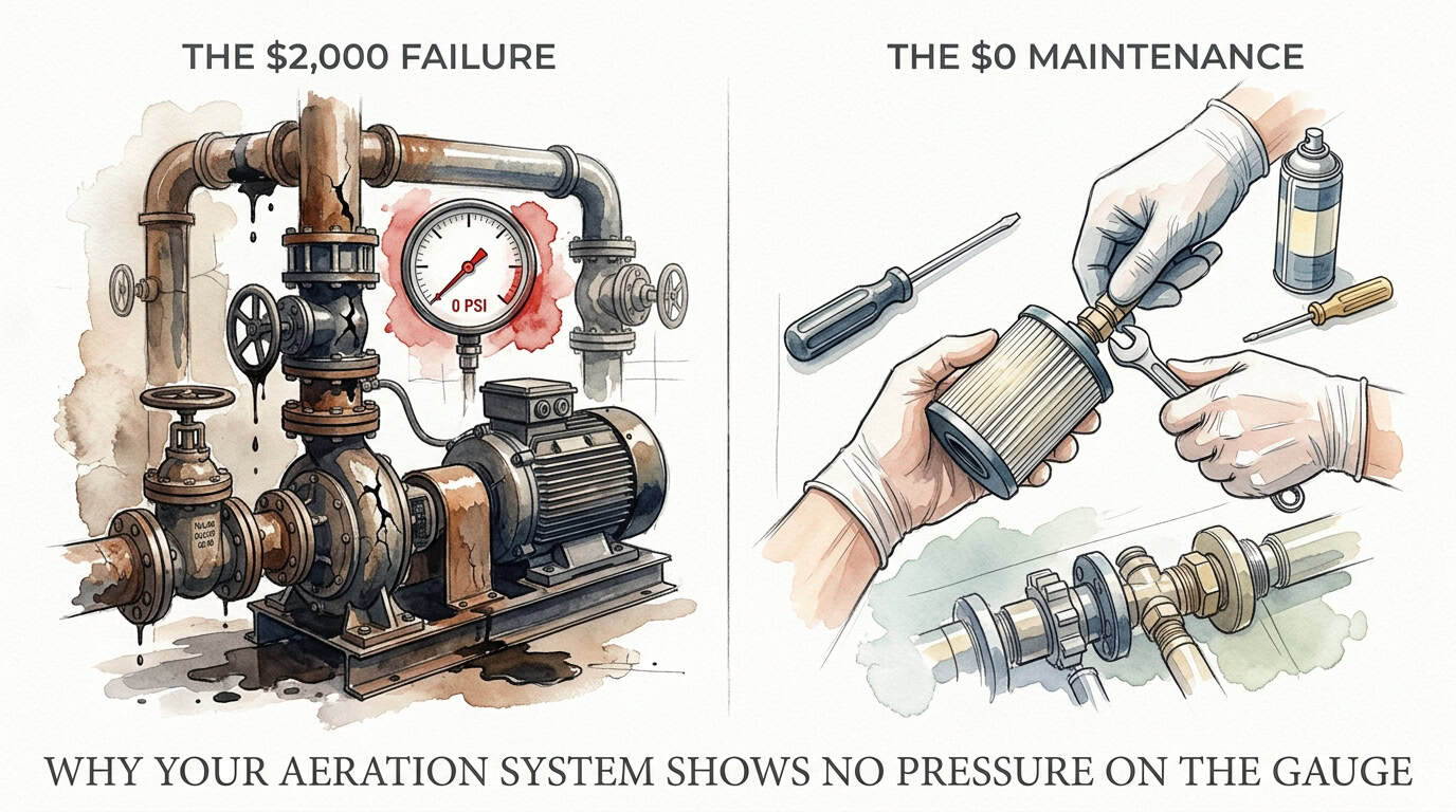
The $2,000 Failure vs. The $0 Maintenance
The financial discrepancy between reactive and proactive maintenance is significant. A standard 1/2 HP rocking piston compressor may cost between $600 and $1,200, while a larger industrial unit can exceed $2,500. Conversely, a comprehensive rebuild kit typically costs between $50 and $150.
| Component | Proactive Maintenance (Rebuild) | Reactive Replacement (New Unit) |
|---|---|---|
| Direct Cost | $50 – $150 | $600 – $2,500 |
| Time Requirement | 30 – 60 Minutes | Varies (Sourcing + Shipping) |
| System Downtime | Minimal | High (Potential Fish Kill Risk) |
| Tools Needed | Basic Screwdriver/Hex Key | Wrenches/Wiring Tools |
Choosing to rebuild a unit at the first sign of pressure drop—even if it hasn’t hit zero yet—saves the cost of the motor and prevents the ecological “cost” of a total oxygen crash in the water body.
Practical Tips for System Optimization
- Perform a Soap Test: If the compressor passes the block test but the gauge shows zero when connected to the lines, spray soapy water on all manifold fittings. Bubbles indicate a leak that is bleeding off the system’s pressure.
- Check Valve Orientation: Ensure that the internal flapper valves or reed valves are installed in the correct direction. If the intake and exhaust valves are swapped during a rebuild, the unit will produce no pressure.
- Monitor Amperage: Use a clamp-on ammeter to check the motor’s draw. A motor drawing significantly less than its rated amperage often indicates it is “freewheeling” because there is no load (due to a major leak or failed seals).
- Record Baseline Data: Write the “New System” pressure on the inside of the compressor cabinet. This provides a reference point to identify when a 1-2 PSI drop occurs, signaling it is time for a rebuild before the gauge hits zero.
Advanced Considerations: Friction Loss and Depth
Serious practitioners must account for friction loss when interpreting gauge data. Small-diameter tubing (e.g., 3/8″) over long distances (e.g., 200 feet) can add 1 to 2 PSI of “artificial” pressure to the gauge. If the gauge reads 5 PSI but the pond is only 4 feet deep, the compressor is working harder than necessary due to pipe friction.
If a gauge reads zero, but you see bubbles in the pond, the system likely has a major leak in the weighted airline. The air reaching the diffuser is only a fraction of the total output. In this scenario, the hydrostatic pressure of the water is higher than the resistance of the leak, so the air takes the easier path out of the broken pipe, leaving the gauge unable to register the remaining low-volume flow.
Scenario: The 12-Foot Pond Failure
Consider a system aerating a pond with a maximum depth of 12 feet. The expected pressure is 5.2 PSI (12 / 2.31) plus roughly 0.5 PSI for the diffuser, totaling 5.7 PSI. If the gauge suddenly reads zero, the technician performs a block test. The gauge stays at zero. Upon opening the compressor, they find a ruptured EPDM diaphragm.
The technician replaces the diaphragm and the flapper valves. Upon restart, the gauge climbs to 8.5 PSI—higher than the original 5.7 PSI. This indicates that while the diaphragm was the cause of the zero-pressure failure, the original cause of the rupture was likely a clogged diffuser. The high backpressure (8.5 PSI) stressed the rubber until it failed. Cleaning the diffuser membranes with a muriatic acid solution or vinegar restores the system to its healthy 5.7 PSI baseline.
Final Thoughts
A zero-pressure reading is a diagnostic starting point, not a death sentence for your aeration equipment. By systematically checking the gauge port, the integrity of the airlines, and the internal seals of the compressor, most failures can be resolved without replacing the entire power unit. The mechanics of aeration are simple: air follows the path of least resistance, and the gauge merely reports how much resistance is found.
Consistent maintenance of intake filters and biannual seal inspections are the most effective strategies for preventing total pressure loss. Understanding the relationship between water depth, friction loss, and mechanical wear allows you to manage your system with data rather than guesswork. Applying these diagnostic steps will ensure that your motor continues to provide the necessary oxygenation for your aquatic environment at peak efficiency.
When you encounter a dead gauge, remember that the motor is often still functional. The mechanical gaps are usually found in the smallest components—a torn $20 rubber part or a clogged $10 filter. Master these basics, and you will significantly extend the service life of your aeration infrastructure.